
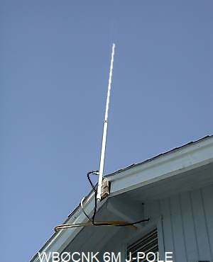
This article provides details on building a 6 Meter J-Pole antenna using PVC pipe for an enclosure.
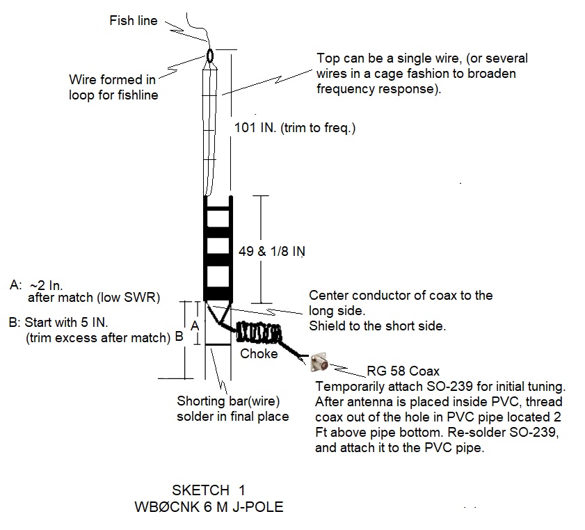
Sketch 1 below, shows the basic electrical layout, which uses flat 450 ohm Window Line
for the tuning stub.
Sketch 2 below, shows the overall construction of the J-Pole antenna.
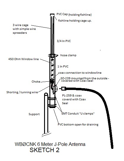
I used window line for the tuning stub, and a 3 wire cage portion above it to help broaden the frequency range. (I used spreaders made out of stiff wire to spread the 3 wires into a crude cage format).
For an enclosure, I used 1 Inch PVC pipe on the bottom (around the tuning stub portion), and ¾ Inch PVC pipe for the top (around the narrower cage portion). This helps reduce the wind profile and weight of the overall antenna. When joining the sections with PVC cement, I followed up with a hose clamp at the overlap joint to add strength. (My initial try without the clamp failed at the joint during a high wind (it split and folded the PVC over at the joint).
Many J-pole articles have you move or adjust the coax attachment point on the tuning stub for obtaining a low SWR. I instead soldered the coax in place, and then used the adjustable shorting bar method. Tuning by sliding a shorting bar(wire) to obtain a low SWR, then soldering it I think is a much easier method of tuning.
A Coax Choke is needed for this type of antenna to work properly.
I wound 9 turns of coax on a small ½ In mandrel, and held it together with tape, so that it would fit inside the bottom PVC. The coiled choke resides an inch or so below the feed point of the window line. (The tuning stub runs along side and below the choke.)
After assembling the window line tuning stub and the wire cage portions,I performed initial "ball-park" tuning before placing it in the PVC. Both the wire cage length, and location of the shorting bar are adjusted at this point. Remove a 2 Inch section of insulation from the window line starting approximately ½ inch below the feed point. Wrap the shorting bar wire around the tuning stub where the insulation was removed (a turn or two around each wire while maintaining the window line width), but don't it solder yet. Temporarily attach a SO-239 connector to the coax from the choke, and solder the other end of the choke to the tuning stub.
For tuning, first slide the tuning bar up and down 1/8 Inch at a time to obtain a low SWR anywhere on or near the band. To adjust to the desired frequency, fold back successive small 1 inch lengths of the top wire (or cage), leaving a loop each time for the fish line to connect to. (The excess wire will be trimmed later). Check and make additional adjustments to the shorting bar wire, as needed, to get a lowest SWR. When satisfied with the initial tuning, cut off the excess top wire(cage), and attach fish line to the cage top. With the the fish line threaded from the bottom of the PVC and out the top, pull the antenna in from the bottom of the PVC, leaving just the tuning bar wire exposed out side the bottom of the PVC.
At this point perform the final tuning. Small adjustments to the tuning bar wire, and top wire(cage) may be needed to compensate for the antenna being placed inside the PVC (mostly the wire cage length).
Once finally tuned, solder the location of the tuning bar wire, remove the previously attached SO-239, and pull the antenna entirely into the PVC, while guiding the loose end of the coax (where the SO-239 was temporarily attached) out the hole in the PVC.
(Pulling the choke and coax up from the bottom of the PVC, and then getting the coax connections out the hole in the PVC for the SO-239 connector, can be a bit of a challenge.)
Permanently solder the SO-239.
The feed point (about 2 Feet up from the bottom of the PVC), is where the SO-239 is mounted from the outside with several screws.
After connecting the PL-259 and feed line coax, I sealed everything, including the square base of the SO-239 (where it is attached to the PVC), as well as the PL-259 and feed line with Coax Seal.
I mounted the antenna using several U-shaped 1 inch EMT Conduit hangers, attached to the open 2 Ft of PVC pipe bottom.
73,
George, WBØCNK