Bench - RSPplay Spectrum Analyser
- Details
- Written by: G Wolfe - KI0KK
Spectrum Analyser APP using an SDRplay RSP1A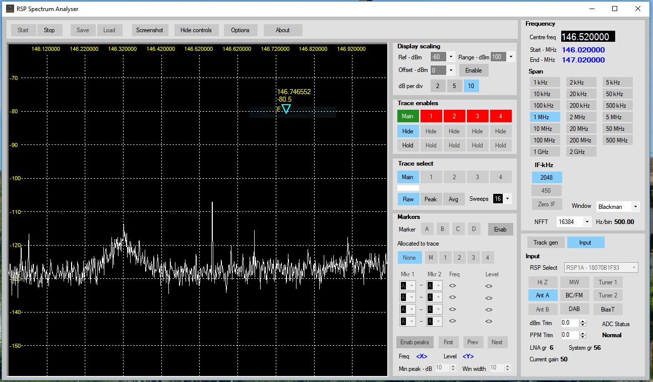
Most hams buy an SDR RCVR to monitor the bands. I found this unique application for the SDRplay RSP1A as a Spectrum Analyser for your test bench. The RSP1A is know for it's level accuracy and high sensitivty. This make the RSP-1A an excellent candidate for making accurate measurements that normallly rrquire a high priced piece of test equipment.
The Spectrum Analyser is based on an Application written by Steve Andrew. This is an Alpha version of the software (v1.0a) and may be downloaded from the SDRplay web page including the User Manual.
The current Devices supported are also listed on the SDRplay web page.
Field Day - Audio Interface Unit Project
- Details
- Written by: G Wolfe - KI0KK
The Santa Fe Trail Amateur Radio Club is undertaking a construction project to improve the Field Day and Special Event operating experience. This article will provide information on the our project without repeating the full source article. A link to the original article is provided at the end of this article.
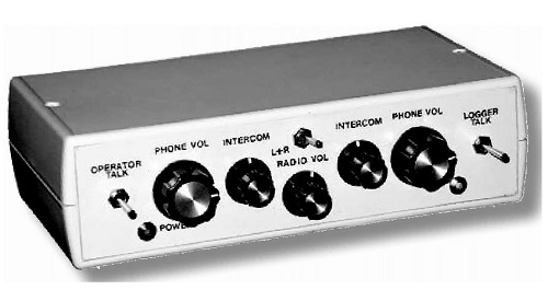
Events such as WW1USA Special Event Station and Field Day can be a fun and yet challenging for operators, loggers and guests. The noisy surroundings and need to concentrate on the chaotic signals on the band requires the use of a headset by the operator. This leaves the logger or the guest with limited ability to hear the contacts. Communications between the operator and logger is also difficult. To solve this problem John Raydo K0IZ designed and published plans in a June 2008 QST article titled "An Audio Interface Unit for Field Day and Contesting".
The K0IZ Audio Interface Unit enhances headset operation by providing the following:
- Operator headphone interface to the radio
- Logger headphone access to the contact audio
- Intercom communications between the operator and logger
- A speaker for visitors to hear the contacts
- Provides individual level control for the operator and logger
- Supports three types of microphones; dynamic, electret and aviation
- Foot switch interface
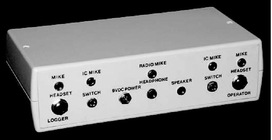
A number of the components have been donated by Jeff Darby, Howard Cripe and Jim Andera. Joe Krout provide the circuit board that started the project and the the QST article. Howard has volunteered to 3D print the project, should be interesting to see the finished enclosure. The remaining parts will be ordered online and hopefully will be here in time to complete the project for the 2019 Field Day. This could be an interesting project for new hams or those interested in building projects to observe or participate in the assembly.
Source: QST June 2008
Author: John Raydo, K0IZ
Title: An Audio Interface Unit for Field Day and Contesting
Click the link above to view a copy of the full article.
The ARRL, QST, provided written permission to use article content (May 7, 2019).
Yaesu FT2DR Wires-X Features
- Details
- Written by: Greg Wolfe
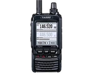
Yaesu's FT2DR HT firmware update has added a new Wires-X feature. With the new firmware the FT-2 is able to plug into a computer and access any Wires-X room. Listening to the YouTube from Yaesu (link shown below) the wired connection to a USB port requires a Yaesu adapter cable to connect to the FT-2. Support for a wireless dongle on the USB port would have made this option a much more versitile?
https://www.youtube.com/watch?

Home Built 6M J-Pole Antenna
- Details
- Written by: George McCarville - WB0CNK
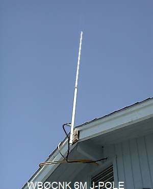
This article provides details on building a 6 Meter J-Pole antenna using PVC pipe for an enclosure.
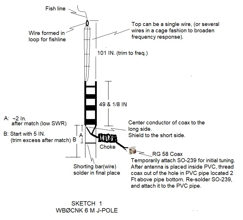
Sketch 1 below, shows the basic electrical layout, which uses flat 450 ohm Window Line
for the tuning stub.
Sketch 2 below, shows the overall construction of the J-Pole antenna.
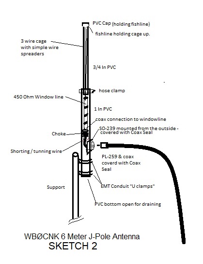
I used window line for the tuning stub, and a 3 wire cage portion above it to help broaden the frequency range. (I used spreaders made out of stiff wire to spread the 3 wires into a crude cage format).
For an enclosure, I used 1 Inch PVC pipe on the bottom (around the tuning stub portion), and ¾ Inch PVC pipe for the top (around the narrower cage portion). This helps reduce the wind profile and weight of the overall antenna. When joining the sections with PVC cement, I followed up with a hose clamp at the overlap joint to add strength. (My initial try without the clamp failed at the joint during a high wind (it split and folded the PVC over at the joint).
Many J-pole articles have you move or adjust the coax attachment point on the tuning stub for obtaining a low SWR. I instead soldered the coax in place, and then used the adjustable shorting bar method. Tuning by sliding a shorting bar(wire) to obtain a low SWR, then soldering it I think is a much easier method of tuning.
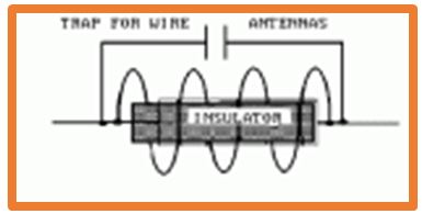
A Coax Choke is needed for this type of antenna to work properly.
I wound 9 turns of coax on a small ½ In mandrel, and held it together with tape, so that it would fit inside the bottom PVC. The coiled choke resides an inch or so below the feed point of the window line. (The tuning stub runs along side and below the choke.)
After assembling the window line tuning stub and the wire cage portions,I performed initial "ball-park" tuning before placing it in the PVC. Both the wire cage length, and location of the shorting bar are adjusted at this point. Remove a 2 Inch section of insulation from the window line starting approximately ½ inch below the feed point. Wrap the shorting bar wire around the tuning stub where the insulation was removed (a turn or two around each wire while maintaining the window line width), but don't it solder yet. Temporarily attach a SO-239 connector to the coax from the choke, and solder the other end of the choke to the tuning stub.
For tuning, first slide the tuning bar up and down 1/8 Inch at a time to obtain a low SWR anywhere on or near the band. To adjust to the desired frequency, fold back successive small 1 inch lengths of the top wire (or cage), leaving a loop each time for the fish line to connect to. (The excess wire will be trimmed later). Check and make additional adjustments to the shorting bar wire, as needed, to get a lowest SWR. When satisfied with the initial tuning, cut off the excess top wire(cage), and attach fish line to the cage top. With the the fish line threaded from the bottom of the PVC and out the top, pull the antenna in from the bottom of the PVC, leaving just the tuning bar wire exposed out side the bottom of the PVC.
At this point perform the final tuning. Small adjustments to the tuning bar wire, and top wire(cage) may be needed to compensate for the antenna being placed inside the PVC (mostly the wire cage length).
Once finally tuned, solder the location of the tuning bar wire, remove the previously attached SO-239, and pull the antenna entirely into the PVC, while guiding the loose end of the coax (where the SO-239 was temporarily attached) out the hole in the PVC.
(Pulling the choke and coax up from the bottom of the PVC, and then getting the coax connections out the hole in the PVC for the SO-239 connector, can be a bit of a challenge.)
Permanently solder the SO-239.
The feed point (about 2 Feet up from the bottom of the PVC), is where the SO-239 is mounted from the outside with several screws.
After connecting the PL-259 and feed line coax, I sealed everything, including the square base of the SO-239 (where it is attached to the PVC), as well as the PL-259 and feed line with Coax Seal.
I mounted the antenna using several U-shaped 1 inch EMT Conduit hangers, attached to the open 2 Ft of PVC pipe bottom.
73,
George, WBØCNK
A Change coming to FT8
- Details
- Written by: Jeff Darby
A big change will be coming to FT8 the on 10-Dec-2018 with the full release of WSJT-X 2.0. This new software incorporates all of the updates added in the prior beta versions of the software. Some of these features are:
1. NA VHF Contest operation with support of grid locators and "/R" (Rover) call signs
2. EU VHF Contest operation with the exchange of 6-digit locators, QSO serial numbers, and "/P" (portable) call signs
3. ARRL Field Day operation with standard Field Day exchanges such as "6A SNJ"
4. ARRL RTTY Roundup operation with standard contest exchanges such as "579 NJ" or "559 0071"
5. Compound and nonstandard call signs (up tp 11 characters); no need for distinctions about "Type 1" or "Type 2" prefixes/suffixes
6. A special "telemetry" message format for exchange of arbitrary information up to 71 bits
7. All features of FT8 DXpedition mode, as in WSJT-X v1.9.1
Additionally this software incorporates a new 77 bit information payload. This will make it incompatible with the current 75 bit payload used in version 1.8.X and 1.9X. With the change in the protocols the reception of calls utilizing the 75 bit payload will eventually drop off as the new software becomes the standard for FT8.
For more information see https://physics.princeton.edu/pulsar/k1jt/wsjtx.html