
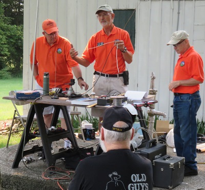
 Instructors - Larry Hall (KDØRIU), Jim Andera (KØNK) and George McCarville (WBØCNK)
Thanks to all who attended the Santa Fe Trail Amateur Radio Club (SFTARC) Antenna Building class/demonstration on September 3, 2021. A morning and afternoon session was presented to about 15 participants with several SFTARC members attending also.
The purpose of the class was to show the basic design elements of a 2m ground plane antenna based on a SO-239 connector and a 20m dipole. The ground plane and dipole are the basic building blocks of many amateur radio antennas.
Jim Andera (KØNK) and George McCarville (WBØCNK) led the class on the 2m ground plane design and construction. Jim discussed the concept of a ground plane antenna and how it works. The design phase identified that the radiating element and radials needed to be about 19.25” with the radials being a little longer. They constructed the antenna with basic tools of wire cutters, tape measure and a 200-watt soldering iron using #14 house wire. Once constructed, the antenna was tested using the MFJ-259 analyzer to trim the antenna to the middle of the 2m band and show how the SWR changes when the radials are bent down vs being perpendicular to the radiating element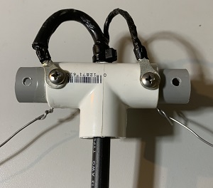 Dipole PVC Center Support
Larry Hall (KDØRIU) led the class on a 20m horizontal dipole and construction. He discussed the radiation pattern of a dipole antenna and how the height above ground and angle between the antenna legs changes the optimal angle of radiation. Horizontal and inverted-V antennas were compared and discussed how they differ. He constructed the 20m dipole using aluminum fence wire (~18 ft to start with) and a center support made from a ½” PVC Tee and short pipe (for added strength). The antenna was raised into the air near a tall tree on the Ensor Park and tested with the MRF-259 analyzer. Changing the angle between the legs of the dipole showed how you can adjust the SWR reading and get a good match to the 50-ohm coax and radio.
Additional discussion talked about how the dipole is the basic building block for other antenna designs like, Off Center Fed Dipole and End Fed Half Wave antennas. Both antenna types are popular with hams and can provide good multi-band operation once their characteristics and limitations are understood.
Additional discussion talked about how the dipole is the basic building block for other antenna designs like, Off Center Fed Dipole and End Fed Half Wave antennas. Both antenna types are popular with hams and can provide good multi-band operation once their characteristics and limitations are understood.
The Off Center Fed Dipole is a regular dipole length for the fundamental band (80 or 40m) but the feed point has been moved from the center of the antenna so that that the antenna will work on more than a single band. Popular designs use a 66/33 ratio and 80/20 ratio (round numbers). For the exact dimensions see the reference link below from Palomar Engineers. These antennas use a 4:1 balun instead of a 1:1 balun that a dipole would normally use. The higher output impedance is what allows the connection point to be moved from the center of the antenna. Baluns are made in both voltage and current style. A current balun will reduce the currents on the outside of the shield on the coax. A coax choke can be added under a voltage balun to achieve the same effect. Either choice will work but you are more likely to find a voltage mode 4:1 balun in the radio stores or on-line.
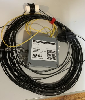 End Fed Half Wave 40m Antenna End Fed Half Wave (EFHW) dipoles are based on the same principle as a center fed dipole but make the coax connection very near one end. An UNUN with a 49:1 ratio (7:1 inductor turns ratio inside, if you build one yourself) is used to couple the expected 2500-ohm impedance for this antenna. See Picture. My experience with this antenna is that a short counterpoise connected to the ground side of the UNUN box will make this antenna have a better SWR match. This counterpoise wire (7ft for mounting height of 35 ft) will help the antenna impedance on the fundamental band, yellow wire in this picture of a 40m antenna. Keep the counterpoise wire in the same plane as the antenna for best operation. For best multi-band operation, a small coil of the antenna wire located 78 inches from the antenna feed connection. Six turns on a 1.25 inch PVC pipe will help move the resonant frequency on the harmonic bands (for 40m antenna this would be 20, 15 and 10m) so that they are closer to the desired section of those bands, whether CW or SSB.
If you are wanting to operate an EFHW on 80m and below (80, 40, 20, 15 and 10) then you need to make sure that the UNUN design has enough inductance to work properly at the fundamental band of 80m. This might be a little on the technical side and reading the reference material from K1RF will help explain what is happening. For EFHW antenna without the coil, you will find the resonant frequency (best SWR) will move up in frequency on the harmonic bands. So, the best match for CW on 80 m will show that the best SWR on the higher frequency bands (especially 20, 15 and 10m) has moved to the top of the band or just above of the SSB frequency portion. The little coil is a big help if you want to do CW on 80 m and do a mix on the other bands. If you want to do SSB on 75m, but the SWR curve has moved too high for the upper bands (40, 20, 15 and 10m) then adding a capacitor to the center of the antenna will be needed. The reference information from K1RF is helpful to explain what is happening. The summary is that the capacitor has more affect on the low band of moving the resonant frequency higher and the inductor will affect the higher bands to a greater degree by moving the resonant frequency lower.
An 80m version of this antenna is long (~135 ft +/-) so tuning will be needed to adjust for the surrounding location and height above ground that it will be operating. Make the long wire several feet longer at the start and then twist it back on itself during the tuning process. Twisting it back on itself is preferred to cutting to an exact length and finding out that it is just a little too short. I know, we have all done that at least once. ?
The EFHW dipole has an advantage in being able to be mounted to a support on the coax end and then only needing one support at the far end. This can work well for many applications that don’t have multiple supports or a convenient way to attach the coax to the center of the antenna.
Participants got the chance to get one of the antennas via a drawing in both classes
Thanks to all involved in the class.
YouTube Video Clips of Class:
Additional Resources:
The End Fed Half-Wave Antenna by Steve Dick, K1RF and OCFD designs from Palomar Engineers.
http://gnarc.org/k1rfs-presentation-on-end-fed-half-wave-antennas/
Palomar Engineers - https://palomar-engineers.com/tech-support/tech-topics/antenna-notes/off-center-fed-dipole-notes